
0
Owner's of the ADTRAN Telephone Total Access gave it a score of 0 out of 5. Here's how the scores stacked up:
Total Access 600 Series System Manual Section 4 User Interface Guide
61200624L1-1B © 2004 ADTRAN, Inc. 151
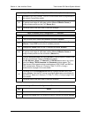
DS0 MAPS > EDIT/VIEW MAP 1 > RBS
Voice applications require signaling information to identify the state of the channel. In some voice
networks a dedicated signaling channel is available to accomplish this (for example, ISDN with a
dedicated D channel). Traditional voice networks may employ Robbed Bit Signaling (RBS), also known as
Channel Associated Signaling (CAS), where a dedicated signaling channel is unavailable. RBS
permanently encodes signaling information by “robbing” a single bit from designated T1 frames and using
them as signaling information carriers. The actual location of the signaling information within the T1
frame depends on the framing format of the T1 circuit. For SuperFrame (SF) framing, the T1 channel is
comprised of 12, 193-bit frames (192 data bits plus a single framing bit). RBS “robs” the framing bits from
the even numbered frames (2, 4, 6, etc) to provide signaling information for that channel. The signaling
bits provided in these frames are known as the A and B signaling bits.Voice termination devices use the
various combinations of the signaling bits to identify the current state of the voice circuit. Each signaling
type (Loop Start, Ground Start, E&M, etc) uses varying combinations of A and B bits to identify the
various states of the circuits such as ringing, on-hook, and off-hook. Extended Superframe (ESF) framing
is similar to SF in operation. Each ESF T1 channel is comprised of 24, 193-bit frames (192 data bits plus a
single framing bit) and allows bit “robbing” in frames 6, 12, 18, and 24. These signaling bits are known as
the A, B, C, and D signaling bits, respectively. Again, voice termination devices use the various
combinations of the signaling bits to identify the current state of the voice circuit.
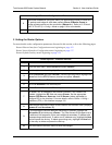
The default value for this parameter is
N/A. Once a port is assigned to a service (using the S
ERVICE
field),
this parameter changes to
O
N
or O
FF
(depending on the selected service). O
N
preserves the signaling bits
between the connections and is typically required for analog voice connections; therefore, for FXS
interfaces,
RBS defaults to O
N
. Additionally, when passing voice circuits with in-channel signaling
through to the DSX-1 interface, signaling bits are preserved by setting
RBS to O
N
. For clear channel
service to the DSX-1 interface (for voice circuits with a dedicated signaling channel and all data) set
RBS
to
O
FF
(which ignores the signaling bits). When S
ERVICE
is set to T1 IAD, the RBS parameter remains at
N/A because RBS is not applicable to data connections.
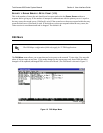
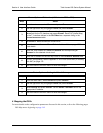
Map 2 menus are identical to Map 1. Please use the menu explanations above for Map 2.


Find Your Products By Category
- Photography
- Video Game
- Computer Equipment
- TV and Video
- Communications
- Automotive
- Portable Media
- Marine Equipment
- Cell Phone
- Baby
- Home Audio
- Fitness & Sports
- Power Tools
- Household Appliance
- Car Audio and Video
- Personal Care
- Kitchen Appliance
- Lawn and Garden
- Musical Instruments & Equipment
- Laundry Appliance
- Outdoor Cooking
Please Login
