
0
Owner's of the ADTRAN Telephone Total Access gave it a score of 0 out of 5. Here's how the scores stacked up:
Section 4 User Interface Guide Total Access 600 Series System Manual
168 © 2004 ADTRAN, Inc. 61200624L1-1B
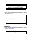
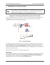
DS0 Mapping Instructions
Step Action
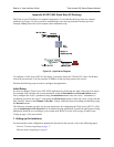
1
From the main menu, select DS0 M
APS
.
2
Verify that the A
CTIVE
M
AP
is set to either M
AP
1 or M
AP
2. This is the map that
is actively running on the unit. The unit has the ability to store two maps.
• To edit the current map, press <E
NTER
> on E
DIT
/V
IEW
M
AP
1 to view the
map. (If Map 1 is the Active Map)
• To edit the standby map, press <E
NTER
> on E
DIT
/V
IEW
M
AP
2 to view the
map. (If Map 2 is the Active Map)
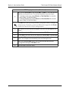
The
DS0
listed on the left side of the menu corresponds to DS0s on the network
T1 interface. The
P
ORT
number identifies the DS0 on the DSX-1 interface. The
DS0
and
P
ORT
do not need to match; DS0s can be cross-connected from the
network T1 to any DS0 on the DSX-1 interface.
3
Scroll down to the DS0 that will be mapped. (Any DS0 can be mapped to the
DSX-1 interface.)
4
Set the S
ERVICE
for the DS0 that you are mapping to DSX-1.
5
Set the P
ORT
of the DS0 that you are mapping. The port number entered
specifies the DS0 on the DSX-1 interface and can be set to any available DS0.
When mapping voice circuits with dedicated signaling channels, be sure to
map the signaling channel to the proper DS0 on the DSX-1 interface. For
example, ISDN D channel signaling is normally carried on DS0 24. Unless the
equipment connected to the Total Access 6XX DSX-1 interface has been
specifically programmed, it will expect a D channel on DS0 24. Map DS0 24 to
Port 24 to provide the D channel in the appropriate timeslot.
6
Set RBS to O
FF
or O
N
depending on the application. When passing voice
circuits with in-channel signaling through to the DSX-1 interface, signaling bits
are preserved by setting RBS to O
N
. For clear channel service to the DSX-1
interface (for voice circuits with a dedicated signaling channel and all data) set
RBS to O
FF
(which ignores the signaling bits).
7
Map all the DS0s as desired, and exit this menu by pressing the left arrow
button. Your changes will automatically save when exiting the map.
8
Make sure the A
CTIVE
M
AP
is set to the correct map (the map you want
running) before exiting the DS0 M
APS
menu.
9
Left arrow back to the main menu.


Find Your Products By Category
- Photography
- Video Game
- Computer Equipment
- TV and Video
- Communications
- Automotive
- Portable Media
- Marine Equipment
- Cell Phone
- Baby
- Home Audio
- Fitness & Sports
- Power Tools
- Household Appliance
- Car Audio and Video
- Personal Care
- Kitchen Appliance
- Lawn and Garden
- Musical Instruments & Equipment
- Laundry Appliance
- Outdoor Cooking
Please Login
