

0
Owner's of the ADTRAN Telephone Total Access gave it a score of 0 out of 5. Here's how the scores stacked up:

Section 4 User Interface Guide Total Access 600 Series System Manual
106 © 2004 ADTRAN, Inc. 61200624L1-1B
C
ONNECTION
(V35) > S
ETUP
> S
ETUP
Use these menus to configure the Protocol mapping, DE map, and FECN map for the V.35 PVC
connections.
C
ONNECTION
(V35) > S
ETUP
> S
ETUP
> P
ROTOCOL
M
APPING
Network providers have the ability to provision each PVC pair with an encapsulation mode
to ensure interoperability between terminal equipment. The choices are
T
RANSPARENT
or
T
RANSLATION
(def).
T
RANSLATION
mode is most common and carries multiple upper layer
protocols over Frame Relay and ATM PVCs.
C
ONNECTION
(V35) > S
ETUP
> S
ETUP
> DE M
AP
Maps Frame Relay Discard Eligible (DE) bit to the ATM Cell Loss Priority (CLP) bit. The
choices are
DE = 0, DE = 1, and C
ONVERT
(map DE TO CLP). The factory default setting is
DE = 0.
C
ONNECTION
(V35) > S
ETUP
> S
ETUP
> FECN M
AP
Allows mapping of Frame Relay FECN (Forward Explicit Congestion Notification) bit to
ATM EFCI (Explicit Forward Congestion Indicator) bit. The choices are
NO
MAP
FECN and
MAP
FECN. The factory default setting is
NO
MAP
FECN.
C
ONNECTION
(V35) > S
ETUP
> DLCI M
APPING
Use these menus to configure the DLCI mapping for the PVC from the T1 network interface to
the V.35 interface.
C
ONNECTION
(V35) > S
ETUP
> DLCI M
APPING
> M
AP
Displays the DLCI Map number and is used as an index for multiple listings. The first map
entry listed is 1, the next is 2, etc. All map numbers assigned will be sequential.
C
ONNECTION
(V35) > S
ETUP
> DLCI M
APPING
> A
CTIVE
Enables FR/ATM mapping and data passing between the V.35 FRFx connection and the
ATM PVC on the network interface. If set to
N
O
, data will not pass from the network to the
configured V.35 endpoint. By default, this field is set to
Y
ES
to allow data to pass as soon as
the connection is configured.
C
ONNECTION
(V35) > S
ETUP
> S
ETUP
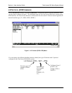
> I
NTERFACE
The T1 interface is ATM[0.0] which represents the T1 physical and logical ports respectively.
This is an identifier for the system to document the T1 network end of the logical link
between the network port and the V.35 interface.


Find Your Products By Category
- Photography
- Video Game
- Computer Equipment
- TV and Video
- Communications
- Automotive
- Portable Media
- Marine Equipment
- Cell Phone
- Baby
- Home Audio
- Fitness & Sports
- Power Tools
- Household Appliance
- Car Audio and Video
- Personal Care
- Kitchen Appliance
- Lawn and Garden
- Musical Instruments & Equipment
- Laundry Appliance
- Outdoor Cooking
Please Login
