
0
Owner's of the ADTRAN Telephone Total Access gave it a score of 0 out of 5. Here's how the scores stacked up:
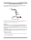

Total Access 600 Series System Manual Section 4 User Interface Guide
61200624L1-1B © 2004 ADTRAN, Inc. 171
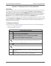
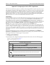
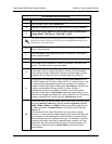
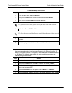
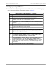
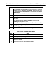
FXS Interface Setup Instructions
Step Action
1
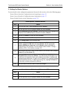
From the main menu, select I
NTERFACES
.
2
Highlight the C
ONFIG
menu for the FXS interface and press <E
NTER
>.
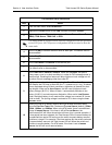
3
Right arrow to select M
ODE
and choose L
OOP
S
TART
, G
ROUND
S
TART
,
T
ANDEM
(E&M), TR08 S
INGLE
, TR08 UVG, or DPO.
This mode should be set based on the network configuration and the
operation of each FXS port. All FXS ports are independent and do not
need to have the same mode.
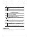
4
Set the T
X
(dB) or transmit direction level for each port. The default
value is recommended.
5
Set the R
X
(dB) or received direction level for each port. The default
value is recommended.
6
Set the S
VC
M
ODE
to I
N
S
ERVICE
to activate the port.
7
Set the L
INE
Z (line impedance) of each port based on the size of the
network. The default value is recommended.
8
Set the M
SG
I
ND
to D
ISABLE
or E
NABLE
. When set to E
NABLE
, talk path is
always open, even in on-hook conditions, in order for FXS message
tones to pass through. Disabling this feature will allow higher on-hook
voltage but will not allow on-hook messaging other than caller ID.
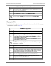
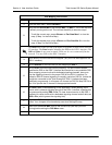
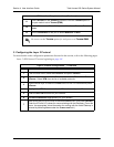
9
Configure the on-hook battery voltage using the B
ATT
M
ODE
field. For
most IAD installs, the FXS loop is short with 6 to 7 V present on tip / ring.
To reduce power dissipated during off-hook conditions, the battery is
lowered for short loop lengths. When set to A
UTO
S
WITCH
, the IAD uses
a higher on-hook battery voltage (48-52 V). When off-hook, it
automatically switches to low battery (24-26 V) to minimize power
dissipation. When set to L
OW
B
ATTERY
mode, the higher battery is not
used and the voltage is a constant 26 V even while on-hook. The tip/ring
voltage is reduced to 26 V when using the L
OW
B
ATTERY
mode.
10
Specify the interval of battery removal during a forward disconnect state
using the F
WD
D
ISC
T
IMER
field. Choices are F
OLLOW
S
WITCH
(default),
500
MS
, 750
MS
, 1000
MS
, and 2000
MS
. When using ATM mode, there is
an additional choice of I
GNORE
S
WITCH
. If the timer is set to F
OLLOW
S
WITCH
, the
Total Access 6XX will follow the switch at all times; this is normal
operation. If a time period has been selected, the Total Access 6XX will
remove battery for the specified time period OR as long as the switch
requests battery removal, whichever is longer. For example, if the timer
expires but the switch continues to request battery removal, the Total
Access 6XX will follow the switch and continue to remove battery. For
ATM mode, if the timer is set to I
GNORE
S
WITCH
, the IAD will never
remove battery.


Find Your Products By Category
- Photography
- Video Game
- Computer Equipment
- TV and Video
- Communications
- Automotive
- Portable Media
- Marine Equipment
- Cell Phone
- Baby
- Home Audio
- Fitness & Sports
- Power Tools
- Household Appliance
- Car Audio and Video
- Personal Care
- Kitchen Appliance
- Lawn and Garden
- Musical Instruments & Equipment
- Laundry Appliance
- Outdoor Cooking
Please Login
