

0
Owner's of the ADTRAN Telephone Total Access gave it a score of 0 out of 5. Here's how the scores stacked up:

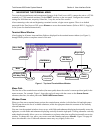

Network Turnup Procedure Total Access 600 Series System Manual
38 © 2004 ADTRAN, Inc. 61200624L1-1B
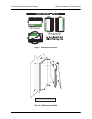
5. MOUNTING OPTIONS
All units may be wallmounted or installed in a table-top application. In addition, the Total Access 612/616/624
units are available for 19- or 23-inch rackmount installations. Wallmount brackets are included with the unit
and are already attached. For a rackmount installation, optional rackmount brackets must be purchased (19” –
P/N 1200627L1, 23” – P/N 1200627L2).
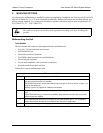
Wallmounting the Unit
Tools Needed
The unit mounts and connects with standard fasteners and hand tools:
• Four #8 x 3/4-inch pan-head wood screws
• Drill and drill bit set
• Flat head screwdriver (medium)
• Two Phillips head screwdrivers (small/medium)
• Wire-wrap gun (optional)
• 25-pair male amphenol cable (customer connection)
• Selected punch-down block and tool
Follow these steps to wallmount the unit:
Be careful not to upset the stability of the equipment mounting rack when installing this
product.
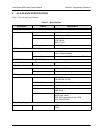
Wallmount Installation
Step Action
1. Decide on a location for the unit. Keep in mind that the unit needs to be mounted at or below
eye-level so that the LEDs are viewable.
IMPORTANT! Mount the chassis with LEDs facing to the side or down as shown in Figure 1 on
page 39 (not facing up).
Refer to Figure 2 on page 39 for a wallmount illustration.
2. Prepare the mounting surface by attaching a board (typically plywood, 3/4” to 1” thick) to a wall
stud.
IMPORTANT! Mounting to a stud ensures stability. Using sheetrock anchors may not provide
sufficient long-term stability.
3. Have someone else hold the unit in position as you install two #6 to #10 (1 1/2” or greater in
length) wood screws through the unit’s brackets and into the mounted board.
4. Proceed to the steps given in Supplying Power to the Unit on page 40.


Find Your Products By Category
- Photography
- Video Game
- Computer Equipment
- TV and Video
- Communications
- Automotive
- Portable Media
- Marine Equipment
- Cell Phone
- Baby
- Home Audio
- Fitness & Sports
- Power Tools
- Household Appliance
- Car Audio and Video
- Personal Care
- Kitchen Appliance
- Lawn and Garden
- Musical Instruments & Equipment
- Laundry Appliance
- Outdoor Cooking
Please Login
