

0
Owner's of the ADTRAN Telephone Total Access gave it a score of 0 out of 5. Here's how the scores stacked up:


Section 4 User Interface Guide Total Access 600 Series System Manual
178 © 2004 ADTRAN, Inc. 61200624L1-1B
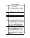
3
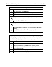
Select I
NTERFACES
and press <E
NTER
>. Use the right arrow key to highlight the
S
ETUP
field for the T1 interface and press <E
NTER
>. Each virtual circuit on the
T1 interface defined in the PVC C
ONFIG
has a separate listing in the R
OUTER
I
NTERFACES
table.
4 Set A
CTIVE
to Y
ES
to activate the virtual circuit.
5 Enter the appropriate VPI and VCI values.
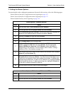
6
Select the desired A
DDRESS
M
ODE
. Refer to Address Mode on page 122 for
more details.
7
Enter the Total Access 6XX L
OCAL
IP A
DDRESS
and corresponding IP
N
ETMASK
for the selected virtual circuit.
8 Enter the IP address for the next hop router in the F
AR
-E
ND
IP A
DDRESS
field.
9
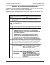
For NAT configuration, refer to Appendix C. RFC1483 Quick Start (IP Routing
with NAT) on page 179.
10 Left arrow back to the main menu to save the changes.
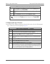
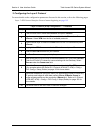
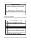
Router Options – Setting the Default Gateway
Step Action
1
From the main menu, select R
OUTER
and press <E
NTER
>.
2
Use the right arrow key to highlight C
ONFIG
and press <E
NTER
>.
3
Select R
OUTES
and press <E
NTER
>. Set the D
EFAULT
G
ATEWAY
field to the
appropriate IP address.
4
Left arrow back to the main menu to save the changes.
Router Options – T1 Interface (L2 Protocol = ATM) (Continued)


Find Your Products By Category
- Photography
- Video Game
- Computer Equipment
- TV and Video
- Communications
- Automotive
- Portable Media
- Marine Equipment
- Cell Phone
- Baby
- Home Audio
- Fitness & Sports
- Power Tools
- Household Appliance
- Car Audio and Video
- Personal Care
- Kitchen Appliance
- Lawn and Garden
- Musical Instruments & Equipment
- Laundry Appliance
- Outdoor Cooking
Please Login
