
0
Owner's of the ADTRAN Telephone Total Access gave it a score of 0 out of 5. Here's how the scores stacked up:


Section 4 User Interface Guide Total Access 600 Series System Manual
156 © 2004 ADTRAN, Inc. 61200624L1-1B
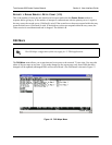
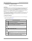
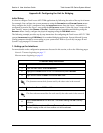
4. Mapping the DS0s
For more details on the configuration parameters discussed in this section, refer to the following pages:
DS0 Map menus beginning on page 149
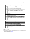
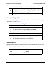
Router Options – T1 Interface (L2 Protocol = FRE or PPP)
Step Action
1 From the main menu, select R
OUTER
and press <E
NTER
>.
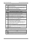
2 Use the right arrow key to highlight C
ONFIG
and press <E
NTER
>.
3
Select I
NTERFACES
and press <E
NTER
>. Use the right arrow key to highlight the
S
ETUP
field for the T1 interface and press <E
NTER
>. Each PVC (frame relay)
on the T1 interface defined in the DLCI M
AP
has a separate listing in the
R
OUTER
I
NTERFACES
table.
4 Set A
CTIVE
to Y
ES
to activate the virtual circuit.
5
Select the desired A
DDRESS
M
ODE
. Refer to Address Mode on page 122 for
more details.
6
Enter the Total Access 6XX L
OCAL
IP A
DDRESS
and corresponding IP
N
ETMASK
for the selected virtual circuit.
7 Enter the IP address for the next hop router in the F
AR
-E
ND
IP A
DDRESS
field.
8
For NAT configuration, refer to Appendix C. RFC1483 Quick Start (IP Routing
with NAT) on page 179.
9 Left arrow back to the main menu to save the changes.
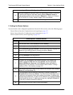
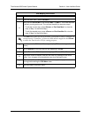
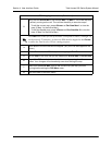
Router Options – Setting the Default Gateway
Step Action
1
From the main menu, select R
OUTER
and press <E
NTER
>.
2
Use the right arrow key to highlight C
ONFIG
and press <E
NTER
>.
3
Select R
OUTES
and press <E
NTER
>. Set the D
EFAULT
G
ATEWAY
field to the
appropriate IP address.
4
Left arrow back to the main menu to save the changes.


Find Your Products By Category
- Photography
- Video Game
- Computer Equipment
- TV and Video
- Communications
- Automotive
- Portable Media
- Marine Equipment
- Cell Phone
- Baby
- Home Audio
- Fitness & Sports
- Power Tools
- Household Appliance
- Car Audio and Video
- Personal Care
- Kitchen Appliance
- Lawn and Garden
- Musical Instruments & Equipment
- Laundry Appliance
- Outdoor Cooking
Please Login
