
0
Owner's of the 3Com Switch 5500-EI gave it a score of 0 out of 5. Here's how the scores stacked up:

Connecting a Redundant Power Supply 39
3Com’s RPS solution uses -48V DC power distribution. The RPS system
provides bulk -48V DC power that is separately distributed to a number
of network switches.
Each RPS consists of a shelf that can house from one to six rectifiers, a
Distribution Module, and a Management Module.
Connecting the
Switch to the
Redundant Power
System
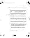
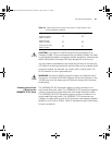
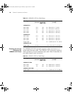
When connecting the RPS to the switch, the circuit breaker and 2-core
cables need to be matched to the switch’s power rating.
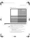
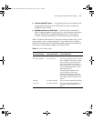
Table 15 shows
the recommended circuit breaker and cable rating for the Switch 5500.
The recommended cable length should not exceed three metres (9.84
feet).
Table 15 Switch 5500 Circuit Breaker and Cable Ratings
WARNING: Make sure to follow the RPS Manufacturers
recommendations when connecting the cable to the RPS.
WARNING: Ensure that the circuit breaker in the RPS is in the open (off)
position when connecting the cable to the RPS and the cable and
connector to the switch.
WARNING: You must ensure that the positive terminal on the switch is
connected to the positive (common) terminal of the RPS and that the
negative terminal on the switch is connected to the negative (circuit
breaker) terminal of the RPS.
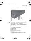
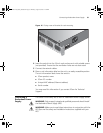
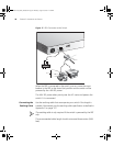
Figure 17 shows how to connect the power supply to the RPS socket in
the back of the switch. Use the cable tie supplied with your switch to
support the cable in the back of the RPS connector as shown in
Figure 17.
Circuit Breaker Minimum 2-Core Cable Diameter
Non PoE 6A C type 18 AWG (solid or stranded cable)
PoE 25A C type 12 AWG (solid or stranded cable)
10014925-AD_S5500_GSG.book Page 39 Thursday, August 16, 2007 12:29 PM


Find Your Products By Category
- Photography
- Video Game
- Computer Equipment
- TV and Video
- Communications
- Automotive
- Portable Media
- Marine Equipment
- Cell Phone
- Baby
- Home Audio
- Fitness & Sports
- Power Tools
- Household Appliance
- Car Audio and Video
- Personal Care
- Kitchen Appliance
- Lawn and Garden
- Musical Instruments & Equipment
- Laundry Appliance
- Outdoor Cooking
Please Login
