
0
Owner's of the 3Com Switch 5500-EI gave it a score of 0 out of 5. Here's how the scores stacked up:


How To Interconnect Units 77
As with all Switch 5500 CLI commands, the format for entering a
command that is port specific is x/y/z, where x = unit number, y = module
number (in the case of the Switch 5500 this will always be 0), z = port
number.
3 Connect the Fabric-enabled ‘up’ port on one Switch 5500 unit to the
Fabric-enabled ‘down’ port on another Switch 5500 unit using the
appropriate connection method for your switch as detailed in
Table 23.
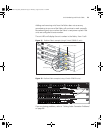
4 To create a fully resilient Fabric: enable the spare Fabric ports on the
top-most and bottom-most units in the Fabric as described in the
previous steps. Then insert a cable into these two Fabric ports to create a
link between the top-most and bottom-most units in the Fabric, as shown
in
Figure 31 on page 79.
This ensures that in the event of a unit failure within the Fabric, the Fabric
will continue working and no “Fabric split” will occur.
Save all configuration settings. From the User View, enter the save
command to save the configuration to your switch.
Stacking Switch 5500G-EI Units
1 Ensure that the switch units that you wish to interconnect have the latest
software agent installed. You can use the display version
command to check this.
2 Connect the stacking cable ‘up’ port on one Switch 5500G-EI unit to the
stacking cable ‘down’ port on another Switch 5500G-EI unit using a
stacking cable (3C17262) or a resilient stacking cable (3C17263).
Note the color code on the stacking cable connectors should match the
color code on the stacking ports, that is, blue for the ‘up’ port that is
connecting to the physically higher unit, and yellow for the ‘down’ port
that is connecting to the physically lower unit.
3 To create a fully resilient Fabric: using the ‘up’ stacking cable port on the
top-most and the ‘down’ stacking cable port on the bottom-most units
insert a stacking cable to create a link between the top-most and
bottom-most units in the Fabric, as shown in
Figure 31 on page 79.
This ensures that in the event of a unit failure within the Fabric, the Fabric
will continue working and no “Fabric split” will occur.
4 Save all configuration settings. From the User View, enter the save
command to save the configuration to your switch.
10014925-AD_S5500_GSG.book Page 77 Thursday, August 16, 2007 12:29 PM


Find Your Products By Category
- Photography
- Video Game
- Computer Equipment
- TV and Video
- Communications
- Automotive
- Portable Media
- Marine Equipment
- Cell Phone
- Baby
- Home Audio
- Fitness & Sports
- Power Tools
- Household Appliance
- Car Audio and Video
- Personal Care
- Kitchen Appliance
- Lawn and Garden
- Musical Instruments & Equipment
- Laundry Appliance
- Outdoor Cooking
Please Login
