
0
Owner's of the 3Com Switch 5500-EI gave it a score of 0 out of 5. Here's how the scores stacked up:

42 CHAPTER 2: INSTALLING THE SWITCH
The Switch 5500 supports 3Com 802.3af equipment. For the latest list of
supported devices, refer to the product page on the 3Com web site at
http://www.3com.com/
For additional information on Power over Ethernet, refer to the Power
over Ethernet Configuration chapter in the Configuration Guide available
on the 3Com Web site. Power over Ethernet management is available
using the web interface or the command line interface (CLI).
Installing and
Removing the
Power Module
Installing the Power
Module
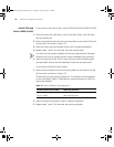
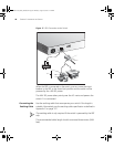
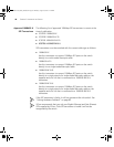
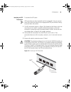
The Switch 5500G Family Power Module is swappable. To install the
power module:
1 Wear an ESD wrist strip, and make that sure it is well grounded.
2 Verify that the Power Module is not installed upside-down (the module
should be installed according to the letters. If the module is installed
upside down, it will not be fully seated due the design of the chassis’
internal structure).
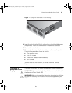
3 Use one hand to hold the handle on the front, and another to hold the
bottom. Slide it gently along the power slot. Push the module until it is
fully seated.
4 Use a Phillips screwdriver to fasten the screws at both sides of the
module.
Removing the Power
Module
To remove the Power Module:
1 Wear an ESD wrist strip, and make sure it is well grounded.
2 Disconnect all power to the switch.
3 Use a Phillips screwdriver to unscrew the screws on both sides of the
module.
4 Use one hand to hold the handle on the front, and another to hold the
top. Pull out the module stably towards you along the power slot until it
is completely apart from the chassis bottom.
10014925-AD_S5500_GSG.book Page 42 Thursday, August 16, 2007 12:29 PM


Find Your Products By Category
- Photography
- Video Game
- Computer Equipment
- TV and Video
- Communications
- Automotive
- Portable Media
- Marine Equipment
- Cell Phone
- Baby
- Home Audio
- Fitness & Sports
- Power Tools
- Household Appliance
- Car Audio and Video
- Personal Care
- Kitchen Appliance
- Lawn and Garden
- Musical Instruments & Equipment
- Laundry Appliance
- Outdoor Cooking
Please Login
