
0
Owner's of the Axis Communications Security Camera Network Camera gave it a score of 0 out of 5. Here's how the scores stacked up:

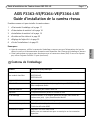
Page 12 AXIS P33-VE Network Cameras Installation Guide
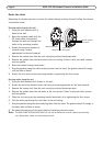
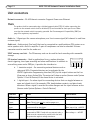
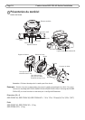
Unit connectors
Network connector - RJ-45 Ethernet connector. Supports Power over Ethernet.
The product shall be connected using a shielded network cable (STP). All cables connecting the
product to the network switch shall be shielded (STP) and intended for their specific use. Make
sure that the network switch is properly grounded. See Electromagnetic Compatibility (EMC) on
page 2 for regulatory requirements.
Audio in - 3.5mm input for a mono microphone, or a line-in mono signal (left channel is used from
a stereo signal).
Audio out - Audio output (line level) that can be connected to a public address (PA) system or an
active speaker with a built-in amplifier. A pair of headphones can also be attached. A stereo
connector must be used for the audio out.
SDHC memory card slot - The SD memory card can be used for local recording with removable
storage.
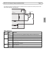
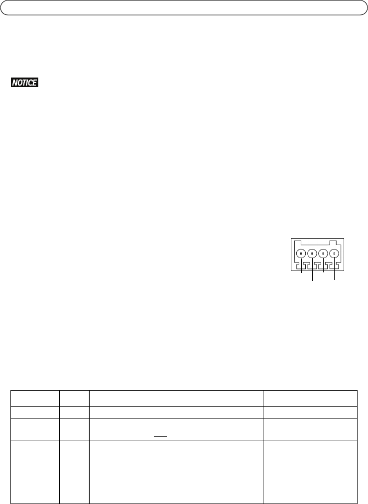
I/O terminal connector - Used in applications for e.g. motion detection,
event triggering, time lapse recording and alarm notifications. In addition to
an auxiliary power and a GND pin, it provides the interface to:
• 1 transistor output - For connecting external devices such as
relays and LEDs. Connected devices can be activated by the
VAPIX® Application Programming Interface (API), by the output buttons on the Live
View page or by an Action Rule. The output will show as active (shown under System
Options > Ports & Devices) if the alarm device is activated.
• 1 digital input - An alarm input for connecting devices that can toggle between an
open and closed circuit, for example: PIRs, door/window contacts, and glass break
detectors. When a signal is received the state changes and the input becomes active
(shown under System Options > Ports & Devices).
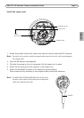
Function Pin Notes Specifications
GND 1 Ground
3.3V DC
Power
2 Can be used to power auxiliary equipment.
Note: This pin can only be used as power out.
Max. load = 50mA
Digital
Input
3 Connect to GND to activate, or leave floating (or
unconnected) to deactivate.
Min. input= 0 to - 40V DC
Max. input=0 to + 40V DC
Digital
Output
4 Uses an open-drain NFET transistor with the source
connected to GND. If used with an external relay, a
diode must be connected in parallel with the load,
for protection against voltage transients.
Max. load = 100mA
Max voltage = + 40V DC
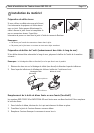
Pin1
Pin2
Pin3
Pin4


Find Your Products By Category
- Photography
- Video Game
- Computer Equipment
- TV and Video
- Communications
- Automotive
- Portable Media
- Marine Equipment
- Cell Phone
- Baby
- Home Audio
- Fitness & Sports
- Power Tools
- Household Appliance
- Car Audio and Video
- Personal Care
- Kitchen Appliance
- Lawn and Garden
- Musical Instruments & Equipment
- Laundry Appliance
- Outdoor Cooking
Please Login
