
0
Owner's of the Axis Communications Security Camera Axis Communications Security Camera gave it a score of 0 out of 5. Here's how the scores stacked up:


AXIS P13 Network Camera Series Installation Guide Page 19
ENGLISH
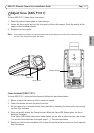
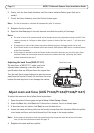
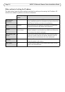
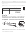
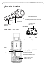
I/O terminal connector - Used in applications for e.g. motion
detection, event triggering, time lapse recording and alarm
notifications. In addition to an auxiliary power and a GND pin, it
provides the interface to:
• 1 digital output – For connecting external devices
such as relays and LEDs. Connected devices can be
activated by the VAPIX® Application Programming
Interface (API), by the output buttons on the Live
View page or by an Event Type. The output will show
as active (shown under Events > Port Status) if the alarm device is activated.
• 1 digital input – An alarm input for connecting devices that can toggle between an
open and closed circuit, for example: PIRs, door/window contacts, glass break detec-
tors, etc. When a signal is received the state changes and the input becomes active
(shown under Events > Port Status).
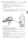
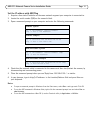
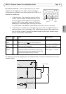
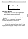
The following connection diagram gives an example of how to connect an auxiliary device to the
network camera.
Function Pin Notes Specifications
GND 1 Ground
3.3 V DC
Power
2 Can be used to power auxiliary equipment.
Note: This pin can only
be used as power out.
Max load = 50 mA
Digital
Input
3 Connect to GND to activate, or leave floating
(unconnected) to deactivate.
Min. input = -40 V DC
Max. input= +40 V DC
Digital
Output
4 Uses an open-drain NFET transistor with the source
connected to GND. If used with an external relay, a
diode must be connected in parallel with the load,
for protection against voltage transients.
Max. load =100 mA
Max. voltage = + 40 V DC
Pin 3
Pin 4
Pin 2
Pin 1
1
2
E.g. push button
3
4
3.3V
max. 50mA
D
S
G


Find Your Products By Category
- Photography
- Video Game
- Computer Equipment
- TV and Video
- Communications
- Automotive
- Portable Media
- Marine Equipment
- Cell Phone
- Baby
- Home Audio
- Fitness & Sports
- Power Tools
- Household Appliance
- Car Audio and Video
- Personal Care
- Kitchen Appliance
- Lawn and Garden
- Musical Instruments & Equipment
- Laundry Appliance
- Outdoor Cooking
Please Login
