
0
Owner's of the Axis Communications Security Camera Axis Communications Security Camera gave it a score of 0 out of 5. Here's how the scores stacked up:
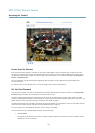
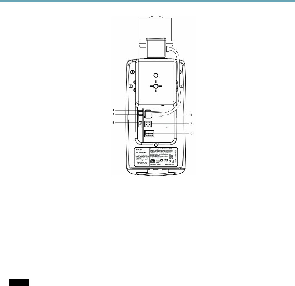
AXIS Q1604 Network Camera
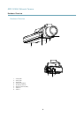
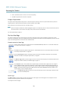
Hardware Overview
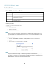
1.
Power LED
2.
Network LED
3.
Control button
4.
Iris connector
5.
Power connector
6.
I/O terminal connector
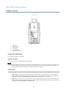
Connectors and Buttons
For technical specications, see page 58.
Network Connector
RJ45 Ethernet connector. Supports Power over Ethernet (PoE).
NOTICENOTICE
NOTICE
The product shall be connected using a shielded network cable (STP). All cables connecting the product to the network switch
shall be shielded (STP) and intended for their specic use. Make sure that the network switch is properly grounded. For
information about regulatory requirements, see RegulatoryInformation, on page 2 .
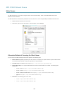
I/O Connector
Use with external devices in combination with, forexample, tampering alarms, motion detection, event triggering, time lapse recording
and alarm notications. In addition to the 0 V DC reference point and power (DC output), the I/O connector provides the interface to:
• Digital output – For connecting external devices such as relays and LEDs. Connected devices can be activated by the
VAPIX® Application Programming Interface, output buttons on the Live View page or by an Action Rule. The output will
show as active (shown under System Options > Ports & Devices) if the alarm device is activated.
• Digital input – An alarm input for connecting devices that can toggle between an open and closed circuit, for example:
PIRs, door/window contacts, glass break detectors, etc. When a signal is received the state changes and the input becomes
active (shown under System Options > Ports & Devices).
7


Find Your Products By Category
- Photography
- Video Game
- Computer Equipment
- TV and Video
- Communications
- Automotive
- Portable Media
- Marine Equipment
- Cell Phone
- Baby
- Home Audio
- Fitness & Sports
- Power Tools
- Household Appliance
- Car Audio and Video
- Personal Care
- Kitchen Appliance
- Lawn and Garden
- Musical Instruments & Equipment
- Laundry Appliance
- Outdoor Cooking
Please Login
