
0
Owner's of the Axis Communications Security Camera Axis Communications Security Camera gave it a score of 0 out of 5. Here's how the scores stacked up:

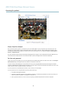

AXIS P3344 Fixed Dome Network Camera
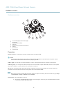
Hardware overview
• ConnectingtoAXISInternetDynamicDNSService.Seepage 40. To connect, press and hold the button for
about 3 seconds.
• Resetting the product to factory default settings. See page 47.
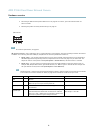
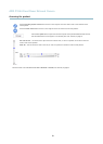
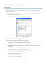
I/O connector
Note
For technical specifications, see page 53.
I/O terminal connector - Use in applications for e.g. motion detection, event triggering, time lapse recording and alarm notifications.
In addition to an auxiliary powe r and a GND pin, the I/O terminal connector provides the interface to:
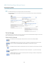
• Digital output — For connecting external devices such as relays and LEDs. Connected devices can be activated by
the VAPIX® Application Programming Interface, output buttons on the Live View page or by an Action Rule. The
output will show as active (shown under System Options > Ports & Devices) if the alarm device is activated.
• Digital input — An alarm input for connecting devices that can toggle between an open and closed circuit, for
example: PIRs, door/window contacts, glass break detectors, e tc. When a signal is received the state changes and
the input becomes active (shown under System Options > Ports & Devices).
Note
The I/O connector is connected to the housing (fan/heater) on delivery, and will trigger an input port event to indicate
a fan or heater error when activated. See Events, on page 32 for information on how to set up an event.
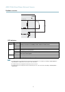
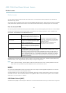
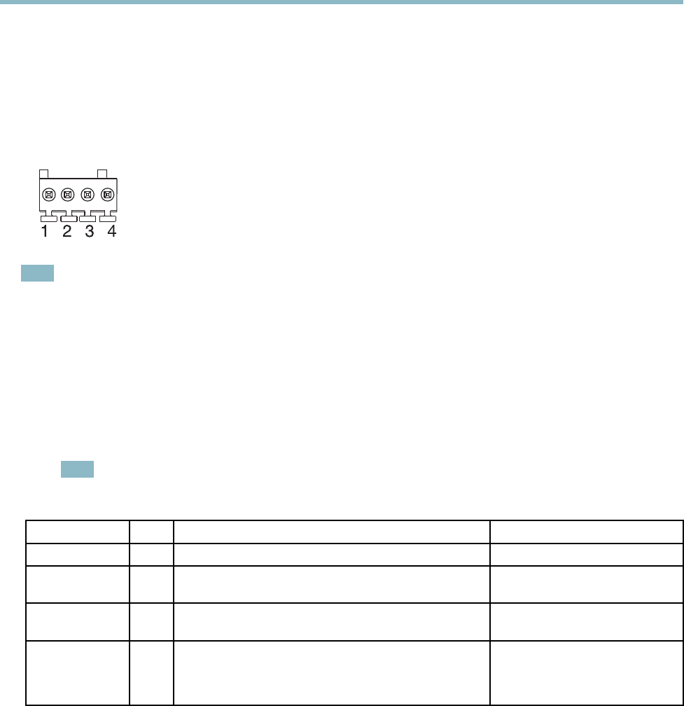
Function Pin Notes
Specifications
GND
1
Ground
3.3 V DC Power
2
Can be used to power auxiliary equipment.
Note: This pin can only be used as power out.
Max load = 50 mA
Digital Input
3
Connect to GND to activate, or leave floating (unconnected)
to deactivate.
0to+40VDC
Digital Output
4
Internal connection to ground when activated, floating
(unconnected) when deactivated. If used with an inductive
load, e.g. a relay, a diode must be connected in parallel with
the load, for protection aga inst voltage transients.
Max load =100 mA
Max voltage = +40 V DC
6


Find Your Products By Category
- Photography
- Video Game
- Computer Equipment
- TV and Video
- Communications
- Automotive
- Portable Media
- Marine Equipment
- Cell Phone
- Baby
- Home Audio
- Fitness & Sports
- Power Tools
- Household Appliance
- Car Audio and Video
- Personal Care
- Kitchen Appliance
- Lawn and Garden
- Musical Instruments & Equipment
- Laundry Appliance
- Outdoor Cooking
Please Login
