
0
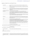
Owner's of the Axis Communications Security Camera 241Q gave it a score of 0 out of 5. Here's how the scores stacked up:
52
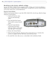
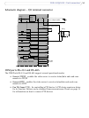
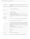
AXIS 241Q/241S - Unit connectors
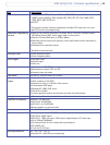
Y/C to BNC cable
AXIS 241Q/241S supports conversion from Y/C (S-video) to composite video using an Y/C
to BNC cable. The cable is available as an accessory - see the Axis Web site at:
www.axis.com. Follow these instructions to connect the Y/C to BNC cable:
1. Connect the BNC connector marked IN to the Video In
connector on the video
server.
2. Connect the BNC connector marked OUT to the Video OUT connector on the
video server.
3. Connect the Y/C connector to the Y/C video unit (S-video).
4. Set the DIP switches on the front panel of the unit to 1=ON, 2=ON, 3=OFF,
4=OFF.
5. Go to AXIS 241Q/241S web pages under Setup > Video & Image > Video Source
and select Y/C (S-video) from the Physical connector drop-down list.
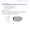
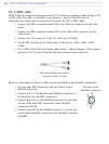
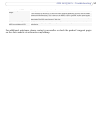
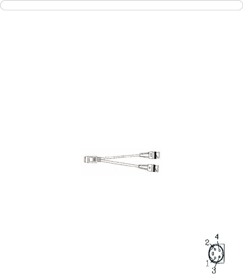
One female MiniDin 4-pol connector
split into two BNC connectors
Below is a description of how the cable can be assembled using standard components:
1. Use two male BNC connectors and one female 4-pole
MiniD
in connector.
2. Connect pin 1, 2 and shield on the MiniDin connector to
the shield on the two BNC connectors.
3. Connect pin 3 (Y) on the MiniDin connector to centre pin
on one of the male BNC connectors, mark this BNC
connector with IN.
4. Connect pin 4 (C) on the MiniDin connector to centre pin
on the other male BNC connector, mark this BNC connector
with OUT.
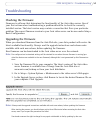
The pins on the
MiniDin connector


Find Your Products By Category
- Photography
- Video Game
- Computer Equipment
- TV and Video
- Communications
- Automotive
- Portable Media
- Marine Equipment
- Cell Phone
- Baby
- Home Audio
- Fitness & Sports
- Power Tools
- Household Appliance
- Car Audio and Video
- Personal Care
- Kitchen Appliance
- Lawn and Garden
- Musical Instruments & Equipment
- Laundry Appliance
- Outdoor Cooking
Please Login
