

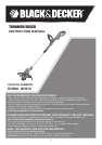
0
Owner's of the Black & Decker Brush Cutter GH900 gave it a score of 0 out of 5. Here's how the scores stacked up:

6
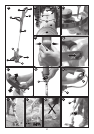
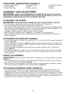
FUNCTIONAL DESCRIPTION (FIGURE A)
1. On/Off Trigger Switch 4. Auxillary Handle 7. Edge Guide Wheel
2. Cord Retainer 5. Collar 8. Guard
3. Power Cord Plug 6. Motor Housing 9. Spool
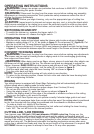
ASSEMBLY AND ADJUSTMENT
WARNING:
UNPLUG THE TRIMMER BEFORE ATTEMPTING TO ATTACH THE GUARD,
EDGE GUIDE OR HANDLE. NEVER OPERATE TOOL WITHOUT GUARD FIRMLY IN PLACE. THE
GUARD MUST ALWAYS BE ON THE TOOL TO PROTECT THE USER.
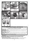
ATTACHING THE GUARD
WARNING: NEVER OPERATE TRIMMER WITHOUT GUARD FIRMLY IN PLACE.
•Turnthetrimmerupsidedownsothatyouarelookingdownatthespool(9).
• Remove the screw from the guard with a phillips screwdriver.
•Turntheguard(8)upsidedownandslideitfullyontothemotorhousing(6).Makesurethe
tabs (10) on the guard engage the ribs (11) on the motor housing as shown in figure B. The
locking tab (25) should have snapped into the housing slot (26).
•Continue to slide the guard on until you hear it “snap” into place.
•Inserttheguardscrewasshowninfigure C to complete the guard assembly.
•Oncetheguardisinstalled,removethecoveringfromthelinecut-offblade,locatedonthe
edge of the guard.
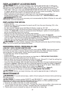
ATTACHING THE AUXILIARY HANDLE
•To attach the handle (4), press in on the buttons (12) on both sides of the upper housing as
shown in figure D.
•Positionthehandleasshowninfigure E, matching up the grooved side of the handle with
the grooved button. Partially push the handle on so that it will hold the buttons in when you
release them with your hand.
•Push the handle completely onto the housing and position it slightly until it “snaps” into
place (figure F).
•Toadjustthehandleupordown,pressinonthebutton(13)andraiseorlowerthehandle.
•The handle should be adjusted so that your front arm is straight when the trimmer is in the
working position.
HEIGHT ADJUSTMENT
CAUTION: Adjust the length of the trimmer to obtain proper working positions as shown
in figure I1.
•The overall height of the trimmer can be adjusted by loosening the collar (5) and rotating it
in the direction of the arrow shown in figure G.
•Move the upper housing straight up or down. When the desired height is achieved, tighten
the collar by rotating it opposite of the direction shown in figure G.
ATTACHING EXTENSION CORD (FIGURE H)
•An extension cord retainer (2) is built into the switch handle that prevents the cord from
coming unplugged. To use this feature, simply double the extension cord about 8 inches
(203mm) from the end, and insert it into the slot (14) in the end of the handle area as shown
in figure H. Hook the loop formed by doubling the cord over the tab (2). Gently tug on the
cord to insure that it is firmly retained in the trimmer’s handle. Plug the receptacle end of the
extension cord into the power cord plug (3) in the trimmer.


Find Your Products By Category
- Photography
- Video Game
- Computer Equipment
- TV and Video
- Communications
- Automotive
- Portable Media
- Marine Equipment
- Cell Phone
- Baby
- Home Audio
- Fitness & Sports
- Power Tools
- Household Appliance
- Car Audio and Video
- Personal Care
- Kitchen Appliance
- Lawn and Garden
- Musical Instruments & Equipment
- Laundry Appliance
- Outdoor Cooking
Please Login
