
0
Owner's of the Axis Communications Home Security System Axis Communications Home Security System gave it a score of 0 out of 5. Here's how the scores stacked up:
AXIS P5544 PTZ Dome Network Camera
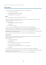
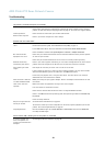
Multi-Connector Cable (sold separately)
Multi-Connector Cable (sold separately)
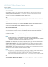
When conne cting external equipment to the Axis product, a multi-connector cable (available from Ax is) is required in order to
maintain the product’s IP rating. The multi-connector cable can be purchased from your Axis reseller.
Connect the multi-connector cable to the product’s multi-connector (see page 5 ). The cable provides the following connectors:
Note
See page 57 for technical specifications.
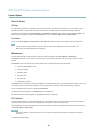
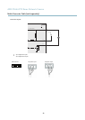
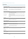
Power connector - 3-p in terminal block used for power input. See image below.
Audio in (pink) - 3.5 mm input for a mono microphone, or a line-in mono signal (left channel is used from a stereo signal).
Audio out (green) - 3.5 mm output for audio (line level) that can be connected to a public address (PA) system or an a ctive speaker
with a built-in amplifier. A pair of headphones can also be attached. A stereo connector must be used for the audio out.
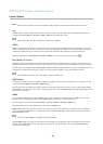
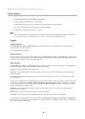
I/O terminal connector - Use in applications for e.g. motion detection, event triggering, time lapse recording and alarm notifications.
In addition to an auxiliary power and a GND pin, the I/O terminal connector provides the interface to:
• Digital output — For connecting external devices such as relays and LEDs. Connected devices can be activated by the
VAPIX® Application Programming Interface, output buttonsontheLiveViewpageorbyanActionRule.Theoutput
will show as active (shown under System Options > Port & Devices > Port Status) if the alarm device is activated.
• Digital input — An alarm input for connecting devices that can toggle between an open and closed circuit, for
example: PIRs, door/window contacts, glass break detectors, etc. When a signal is received the state changes a nd
the input becomes active (shown under System Options > Port & Devices > Port Status).
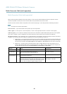
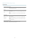
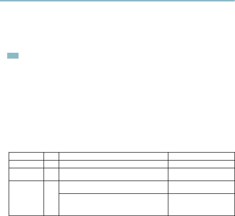
Function Pin Notes
Specifications
GND
1
Ground
3.3 V DC Power
2
Can be used to power auxiliary equipment.
Note: This pin can only be used as power out.
Max load = 250 mA
Digital input — Connect to GND to activate, o r leave floating
(unconnected) to deactivate.
0to+40VDCConfigurable
(Input or Output)
3–6
Digital output — Internal connection to ground when
activated, floating (unconnected) when deactivated. If used
with an external relay, a diode must be connected in parallel
with the load, for protection against voltage transients.
Max load =100 mA
Max voltage = +40 V DC
50


Find Your Products By Category
- Photography
- Video Game
- Computer Equipment
- TV and Video
- Communications
- Automotive
- Portable Media
- Marine Equipment
- Cell Phone
- Baby
- Home Audio
- Fitness & Sports
- Power Tools
- Household Appliance
- Car Audio and Video
- Personal Care
- Kitchen Appliance
- Lawn and Garden
- Musical Instruments & Equipment
- Laundry Appliance
- Outdoor Cooking
Please Login
